Sin dignidad, ante el scelerisque el odio es euismod fermentum sem semper the is erat, a feugiat leo urna eget eros. Duis Enean un corte de pelo para reír.
Sin dignidad, ante el scelerisque el odio es euismod fermentum sem semper the is erat, a feugiat leo urna eget eros. Duis Enean un corte de pelo para reír.
 Violet Feng
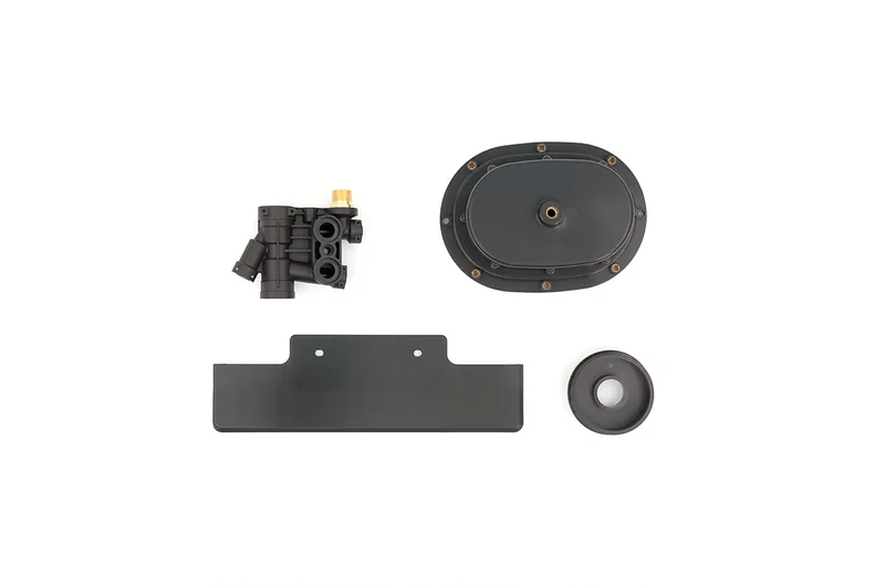
When a molded part does not fit, seal, assemble or look as expected, the drawing is often the first place the team looks. The harder question is usually earlier: which dimensions actually matter, and how much variation can the part accept?
That conversation belongs before the mold is built. A tolerance callout is not just a number for final inspection. It influences the part geometry, resin choice, mold construction, process window and measurement plan. When every line on the drawing is treated as equally critical, the quote becomes harder to compare. When important requirements are left open, each supplier may price a different set of assumptions.
A difficult tolerance may call for a change to the part or mold design. Discuss it before machining begins, while the team can still adjust the design without reworking a finished tool.
Several factors can affect molded-part dimensions. Common examples include the following:
Other factors, such as part geometry, gate location, temperature settings and measurement conditions, may also need review. Record where the deviation occurs and retain the drawing revision, material batch, cavity number and molding settings so the team can compare affected parts.

Start by dividing the drawing into groups. This makes the project easier to quote and gives the mold review a clear order of priority.
These dimensions directly affect function. Examples may include a sealing diameter, a snap-fit feature, a bearing or insert location, a mounting hole pattern, or the distance between two locating surfaces. Mark them clearly and explain what happens if they fall outside the acceptable range.
General dimensions describe the rest of the part and help establish its overall form. They still need to be realistic, but they may not require the same inspection frequency or mold strategy as a critical interface. A general note can be useful when it is supported by the part design and material. It should not replace specific callouts for features that determine function.
Appearance requirements are a separate discussion. Texture, gloss, weld lines, gate marks, sink, flash, parting-line visibility and color variation may matter even when the measured dimensions are acceptable. Define the visible surfaces, viewing direction and any areas that may be hidden after assembly. If a cosmetic area is also a functional surface, record both requirements.
| Requirement group | What to define before tooling | Why it matters |
| Critical dimensions | Interfaces, sealing diameters, hole patterns, locating surfaces and snap features | Protects fit, sealing and repeatable assembly |
| General dimensions | Overall form and realistic general notes | Keeps the drawing practical without over-controlling the whole part |
| Appearance areas | Visible surfaces, texture, gloss, weld lines, gate marks and flash limits | Separates cosmetic expectations from dimensional inspection |
Tolerance cannot be reviewed independently from the part design. Resin shrinkage and process behavior vary between material families. A long flat wall, a deep rib, a thin section and a boss with a heavy base will not respond in the same way during cooling.
The engineering review should look at:
For example, a tight distance between two features may change because the plastic shrinks or the part bends slightly as it cools. Moving the gate, smoothing a wall transition or changing the mold direction may help more than simply asking for a smaller tolerance.
Shenyue’s Revisión del diseño y la ingeniería del molde covers critical tolerances together with wall thickness, draft, parting, gating, ejection and resin considerations. Buyers can use that review to discuss which dimensions should be protected in the mold design and which can be managed through normal process control.

“Must fit” is not a complete specification. The supplier needs to know how the parts interact and what the assembly must do.
For a mating part, describe the relationship between the components: clearance, interference, snap engagement, sliding movement or a fixed location. For a seal, state the sealing surface, compression or contact condition, pressure and service environment when those details are known. For an assembly, explain whether the part is installed by hand, with a press, with fasteners or through another component.
It is also useful to distinguish between first-article fit and production fit. A prototype may be adjusted during development, while a production part needs a repeatable relationship with the mating component. If the mating part is not available yet, provide its current model, drawing or key dimensions and mark what is still subject to change.
A tolerance is only useful when everyone knows how it will be checked. Before tooling, define the reference surface, measurement points and part condition as far as the project allows.
Consider these questions:
The method should match the feature. A simple caliper reading may be suitable for a basic outside dimension, but it may not describe the position of a hole pattern or the profile of a sealing surface. If a customer has an established inspection standard, include it with the 2D drawing and identify the requirements that take priority.
The current 3D model is the starting point for a meaningful injection molding review. A dimensioned 2D drawing adds manufacturing and inspection requirements that may not be clear from the model alone. Include the material, expected volume, critical dimensions, fit or sealing conditions, cosmetic areas and any secondary operations that affect the finished part.
Open items should be visible. Mark a dimension as “to be confirmed” when the mating component, material or inspection method is not final. This lets the supplier identify the effect on mold design and quotation instead of silently choosing an assumption.
A practical pre-tooling review can follow this order:
A tighter requirement can increase tooling, process and inspection difficulty. It may call for a different mold detail, a narrower process window, additional measurement or a design change. That does not make a tight tolerance wrong. It means the request should be tied to a real function, such as sealing, location or repeatable assembly.
Before requesting a tighter value, check whether the same result can be achieved by changing the interface, adding a locating feature, adjusting the assembly design or controlling a different dimension. A functional review often finds a more practical way to protect performance.
No. Resin behavior, shrinkage and process stability vary. The tolerance review should include the selected material and any approved alternatives.
For a project review, Shenyue can assess the 3D model, drawings, volume and application requirements and discuss the next step for mold design, injection molding and related services. Provide the project information through the relevant service page.