Nullam dignissim, ante scelerisque the is euismod fermentum odio sem sempre das ist erat, ein feugiat leo urna eget eros. Duis Aenean ein unverschämtes Risiko.
Nullam dignissim, ante scelerisque the is euismod fermentum odio sem sempre das ist erat, ein feugiat leo urna eget eros. Duis Aenean ein unverschämtes Risiko.
 Violet Feng
A plastic cover rocks on its base, although its length and width are within tolerance. What should be checked next? Another measurement of overall size will not explain the failed fit. The contact surface, the way it is formed in the mold and what happens during molding all need a closer look.
For this hypothetical cover, the injection mold structure review would extend beyond the sizes of the cavity and core. An insert’s position raises a different question from the feeding layout or the release arrangement. Each needs to be considered at the stage where it acts on the part.
Before comparing design options, the buyer and mold team need a common definition of an acceptable part. The injection molding tolerance review sets out the dimensional and measurement questions to settle first.
Start with the troublesome interface on the product drawing. Naming a particular sealing face or mounting pattern gives the designer somewhere to begin. “Make the tool more precise” leaves both the location and the acceptance requirement open.
Take the cover as a hypothetical example. Its contact surface is the feature of interest, but “check that it sits flat” still leaves room for disagreement. A freely supported cover, a cover held in a fixture and an assembled cover are different checking conditions. The agreed acceptance requirement needs to say which one applies.
An appearance check cannot stand in for this decision. Neither can a measurement whose supporting conditions have not been agreed. The discussion needs to end with a checking method that both sides can use.

For a critical dimension, trace its two ends back to the surfaces in the mold. The relationship may involve a cavity and core, an insert or a moving element. Their positions in the assembled tool matter alongside their individual measurements.
A parting line across a functional surface also deserves attention before machining starts. Its location is a design decision to review, rather than something to explain away after samples arrive.
There is no rule that all critical features must come from a single mold component. Some geometries need a more involved arrangement. What matters is being able to identify the forming surfaces and explain how their relationship will be checked.
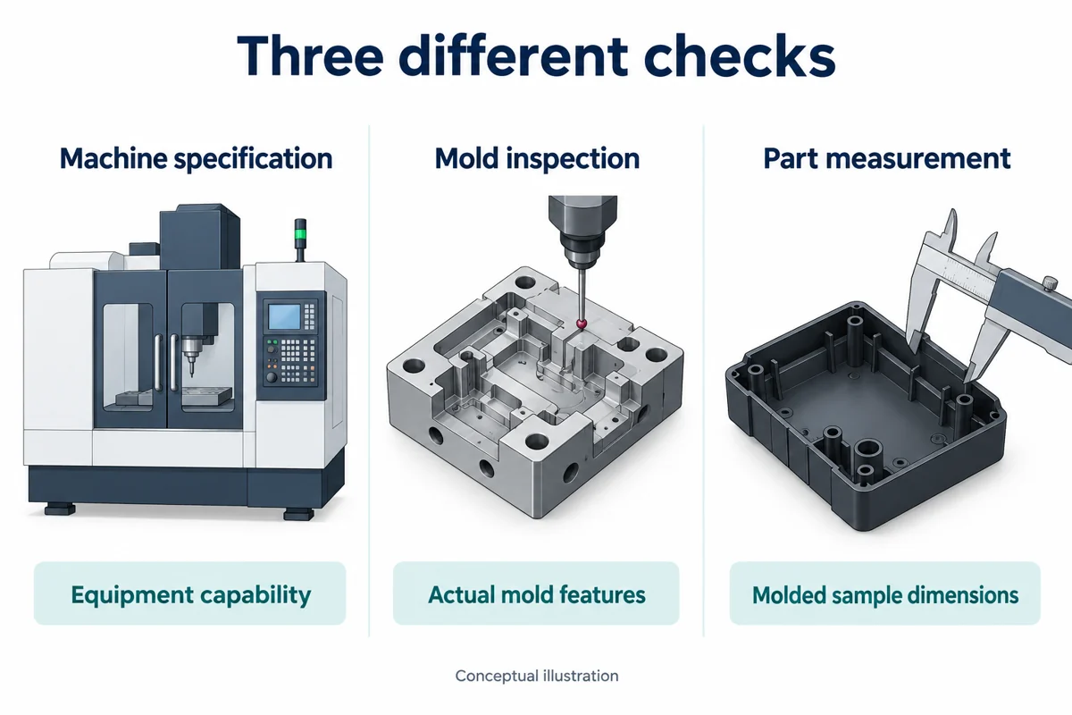
Equipment performance, component measurements and the assembled tool provide different evidence of mold machining accuracy. A machine specification alone does not answer the assembly question.

Runner length and design affect how much pressure is lost before the melt reaches the part. A large loss is possible with long or poorly designed runners. An unbalanced filling pattern can also leave some areas overpacked while flow hesitates elsewhere.
A pressure value on the machine screen cannot describe all of that. A trial at a different pressure can be informative, provided the result is considered alongside the runner layout and filling pattern.
Keep samples identified by cavity when comparing a multi-cavity mold. Mixed samples discard a useful clue before the investigation has begun. Even a clear difference is only a lead: filling, cooling and tool checks are still needed to investigate it.
Der holding pressure guide explains the process adjustments in more detail. Here, the feeding layout needs to be considered before deciding that another pressure setting is the whole answer.
When warpage is suspected, cooling channel positions are worth checking on the mold drawing. How far are the channels from the cavity and from one another? Does the cooling assessment show a local hot spot? These details help investigate uneven cooling, which can contribute to the loss of shape.
For the cover example, mark the region that lifts away from the base. Then compare that observation with the cooling assessment. Include the sample’s support condition with the measurement so someone repeating the check knows how it was done.
An out-of-range number is not enough to choose a tool correction. The next comparison needs samples from agreed production conditions, together with measurements of the relevant forming surfaces. Otherwise, a shape change in the plastic and a location error in the tool can be confused.

Opening the mold does not finish the cycle. The part still has to be removed, and there is a risk of deforming it if it has not cooled sufficiently. Cooling condition is one of the things to check when the suspected movement occurs at this stage.
A mark near a distorted region is worth recording, along with the release sequence. Calling the mark the cause would go further than the evidence allows.
Support during removal is particularly worth discussing around delicate geometry. The mold team needs to consider where ejection force acts and which surfaces have functional or appearance requirements. There is no single arrangement to prescribe without the part geometry.

The resin grade belongs in the mold design discussion from the start. A fiber-filled grade illustrates why: reinforcement can reduce shrinkage, while fiber orientation introduces directional behavior. A dimensional assessment therefore has to take account of flow direction.
Any proposed alternative grade should be identified as well, before it is substituted in production. The team can then check which assumptions may need revisiting. An unchanged tool is not evidence that a different resin will produce the same dimensions.
A useful complaint describes what happened without deciding the cause in advance. These examples show where a review could begin.
| Observed issue | Useful question for the mold review |
| A dimension differs between cavities | Are the same references being used, and what do cavity-specific filling, cooling and tool checks show? |
| A contact face is no longer flat | What does the cooling review show around that region, and how was the sample supported during measurement? |
| A feature shifts near a mold interface | Which components form it, and has their assembled relationship been checked? |
| Distortion is noticed during removal | What do the cooling condition and release arrangement show at the affected area? |
Shenyue’s Werkzeugkonstruktion und technische Überprüfung covers the mold concept, critical features and production constraints. A marked drawing and identifiable samples give that discussion more to work with than “the dimensions are unstable.”
A designer may need extra mechanisms to form a particular geometry. Their presence says little about dimensional control on its own. Ask which features they form and how those features will be verified.
The trial result may change with pressure, but that leaves the original question about structure open. Tool checks and observations of filling, cooling and release are needed before drawing a conclusion about the cause.
Send the drawing revision with the affected feature marked, together with the resin grade, cavity identity, measurement method and trial record. If the part failed during assembly, describe that failure too. A number outside tolerance does not always explain what the buyer could not assemble.
The drawing and sample records are a useful starting point to discuss the affected features with Shenyue. On a new project, identifying these requirements before machining leaves them available for the mold design discussion.