위엄 없음, scelerisque 이전에는 euismod fermentum 증오입니다 sem semper the is erat, a feugiat leo urna eget eros. 뒤이스 에네안 웃음을 위한 헤어컷.
위엄 없음, scelerisque 이전에는 euismod fermentum 증오입니다 sem semper the is erat, a feugiat leo urna eget eros. 뒤이스 에네안 웃음을 위한 헤어컷.
 바이올렛 펑
A plastic housing may look fine until its mounting holes have to line up with another part. If they do not, where should the tooling review begin? Machining is one place to look. The measurement references and molding conditions need to be in the discussion too.
The useful question is not simply how accurate the machining equipment is. It is whether the features that control fit were made, assembled and checked against the right requirements, then confirmed in molded samples.
This article looks at the tooling side of dimensional control. The broader starting point is the injection molding tolerance review, which separates critical dimensions from general and cosmetic requirements.
A machine specification, a mold inspection result and a plastic-part measurement answer different questions.
The machine specification describes an aspect of the equipment’s performance under stated conditions. A mold inspection asks whether the actual cavity, core or insert meets its drawing. A sample inspection checks the plastic part against the product requirements.
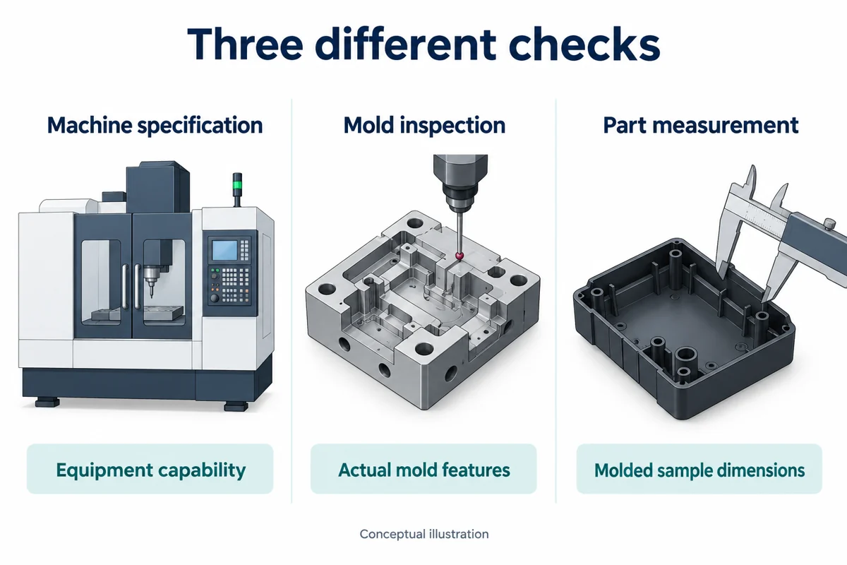
Ask for the record that answers the question at hand. For a disputed hole position, that means a measurement of the relevant feature, not just the machining center’s specification. The molded sample still needs its own check, even after the metal component has passed inspection.
There is also the change from mold geometry to cooled plastic. Shrinkage depends on the material and the part geometry, including wall thickness. An equipment list cannot settle that part of the review.
For a buyer comparing tooling proposals, a better question is: which mold features control the critical interface, and what evidence will be used to accept them?
Consider a hypothetical housing with two locating holes. The assembly needs the holes to sit correctly relative to a mounting face. Checking each hole’s size alone would not answer the whole question. The review also needs to address their positions relative to that face and to each other.

The same thinking applies to the tooling. Which components form the holes? Which surface establishes the reference? Does the dimension involve one component or several assembled components?
These questions give the machining review a useful target. They also help separate an individual feature check from an assembled-tool check. “The inserts were inspected” is incomplete if the disputed relationship concerns the inserts’ positions after assembly.
For an interface formed by several mold elements, bring the parting and insert arrangement into the mold design review. Mark the product dimension and the tool components involved so the discussion stays specific.

The cutting tool and the component it cuts are two separate inspection subjects. Tool setting concerns the cutting tool: its reference, condition and possible wear or breakage. Workpiece inspection concerns the component being made, including its features, size and position.
A useful inspection discussion should say which of those checks is being described. It should also identify the drawing revision and the features covered. Without that context, “checked during machining” can mean several different things.
For critical mold geometry, the following questions are worth settling before manufacture:

The answer need not be a long report for every surface. Inspection effort should reflect the effect of a deviation. A locating feature that controls assembly deserves a different discussion from a surface with a generous clearance.
Suppose one cavity repeatedly produces a feature outside its limit while the others remain acceptable. That is a reason to compare the affected cavity with the others. That pattern alone does not identify the cause.
The review can start with cavity identity, drawing revision and the measured mold features. Material and process conditions remain part of the comparison. Before choosing between a tool inspection, a repeat trial and a setting change, put those records side by side.
Now consider a different trial: the measured dimension changes along with the molding conditions. Which trial should the proposed metal correction be based on? Agree that baseline first; otherwise the target itself remains unsettled.
그만큼 holding pressure article covers one part of that process discussion. Use it alongside the tool measurements when reviewing a dimensional fault; neither discussion settles the cause on its own.
A resin change is a good reason to revisit the shrinkage allowance used for the tool. Record the grade, not just a broad material name, and check the assumptions against the revised requirements.
Shrinkage can differ with geometry and direction. For a locating hole or assembly face, review the dimension that matters rather than relying on one overall volume-change figure. Keep the material grade and condition with the sample record.
For a tooling correction, the practical record should connect four things: the current tool revision, the material used in the trial, the affected product dimension and the proposed change. A note such as “adjust the hole” leaves too much open. A marked feature and an agreed target make the decision reviewable.
After correction, the sample check should address the intended result. If the purpose was to improve an assembly fit, the dimensional report and the relevant fit check should be considered together. The acceptance method belongs in the project agreement.
Shenyue’s mold tooling process connects component machining, fitting, assembly and trial. Sample measurements and process observations guide the next correction.

To make that discussion specific, the project brief should identify the critical dimensions, resin, drawing revision and required documentation. For a troublesome interface, a marked view of the mating parts is useful. Explain what happens at assembly: does the part interfere, sit too loosely or fail to locate?

Decide how the next trial will be compared with this one. The measurement sheet should identify the cavity and sample, with tool or material changes noted alongside. Leave unresolved items visibly open until a decision has been recorded.
No. A measured mold feature and a measured plastic sample are different results. Material behavior and molding conditions still affect the part, so include both sets of measurements in the review.
The requirement should follow the part’s function. Identify the features that control fit and agree their inspection needs. Applying one demanding value everywhere does not explain which relationships matter.
After the affected dimension, measurement method, material and trial baseline are clear enough to support a decision. A sample outside its limit starts an investigation; it does not by itself identify the correct metal change.
For a new tool or a dimensional issue on an existing project, contact Shenyue with the current drawings, material details and marked critical features. That gives the tooling review a concrete question to resolve.